
Build a simple map and drive it
A small purpose-built map is ideal when you want to test a route without the noise of a city-sized road network. In this tutorial, you create a straight approach and a gentle bend, connect their lanes, and test the result with a vehicle.
Learning outcomes: After this example, you can create roads, edit their geometry and lane metadata, connect lanes, control the map overlays, place a trajectory on a lane, save your work, and choose suitable export formats.
Before you start: Map mode
scenario.generator opens in Trajectory mode. Select Switch to map mode above the central canvas to edit roads instead of actors. Entering Map mode does not create or change anything by itself, so you can safely switch back to Trajectory mode at any time.
This tutorial creates a map from scratch. To start from an existing
ASAM OpenDRIVE file instead,
open Load map and choose either a bundled map with Load default or a
local .xodr file with Upload map. You can also follow
Create a rainy pedestrian crossing.
1. Draw the approach
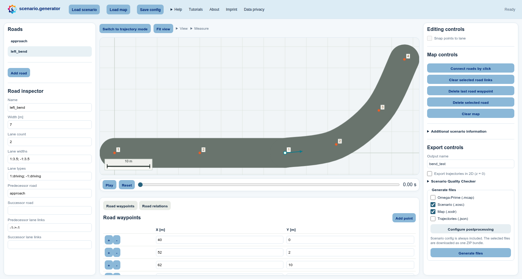
- Select Switch to map mode above the central canvas. The list on the left changes from Actors to Roads, and Map controls appear on the right.
- Select a position near the left side of the central canvas. Use a pointer, or focus the canvas, move its keyboard cursor with the arrow keys, and press Enter. Because no map exists yet, this creates the first road and its first reference-line point. You can also select Add road below the Roads list before choosing a canvas position.
- Add two more points in a straight line towards the centre of the canvas. You can drag the orange road points to refine the shape or enter exact coordinates in the Road waypoints table below the canvas.
- In the Road inspector below the road list on the left, you can rename
the road to
approach. Configure its two lanes as follows:- Lane count: enter
2to create two lanes around the road's reference line. - Lane widths: enter
-1:3.5; 1:3.5. Each entry useslane ID:width in metres, and the semicolon separates the lanes. Looking along the reference line in the order in which you clicked its points, lane-1is on the right and lane1is on the left. Both lanes are3.5 mwide, resulting in a total road width of7 m. The signs identify the side of the reference line; they do not directly specify the driving direction. - Lane types: enter
-1:driving; 1:driving. This uses the same lane IDs and declares both lanes as driving lanes. The lane type affects the map representation, lane snapping, and the exported OpenDRIVE data.
- Lane count: enter
2. Add and connect the bend
- Select Add road below the Roads list on the left. In the Road
inspector, you can rename it to
left_bendand give it the same lane count, widths, and types as the approach. - On the central canvas, place the first point just beyond the end of the
first road (
approachif you renamed it), then select three or four positions that form a gentle left-hand bend. Canvas positions accept either pointer selection or the keyboard cursor and Enter. The exact number of points is not important; use enough points to describe a smooth reference line. - Open View above the canvas. Under Map view, enable Road points, Lane numbers, Road centerlines, and Road connections.
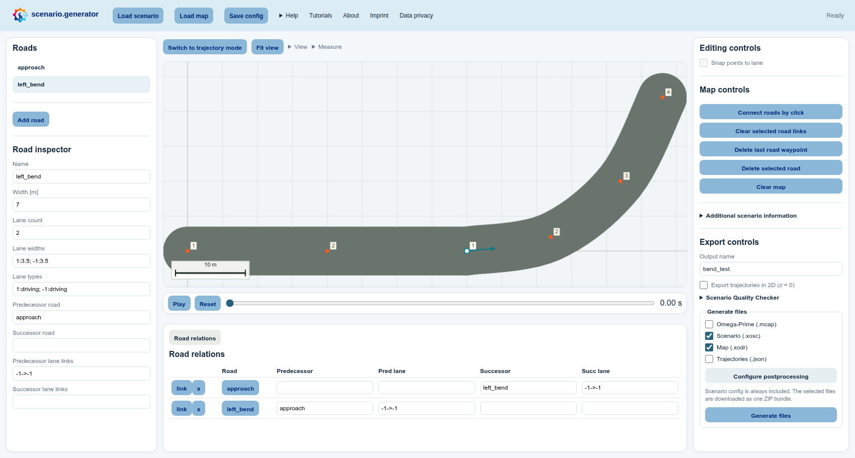
- Under Map controls on the right, select Connect road lanes. On the canvas, first select the outgoing lane of the first road, then the matching lane on the second road. Both selections work with a pointer or the canvas keyboard cursor and Enter.
To inspect or edit the connection precisely, open View → Table view above the canvas and enable Road relations table. In the table below the canvas, check the predecessor and successor road names and their signed lane links.
3. Test-drive the map
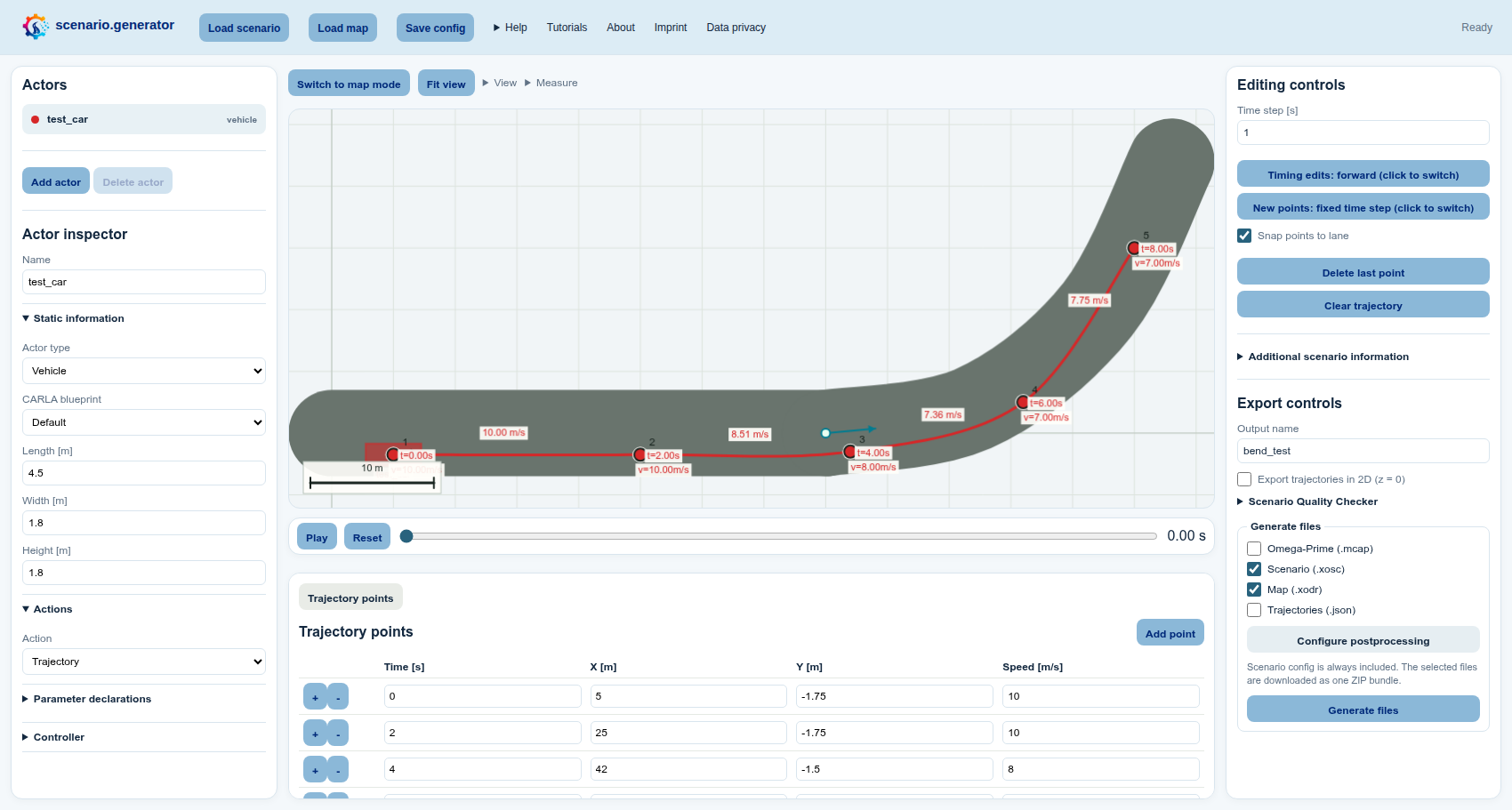
- Select Switch to trajectory mode above the canvas. In the Actors list on the left, select one vehicle.
- Under Editing controls on the right, enable Snap points to lane.
Then choose how to adapt the vehicle trajectory:
- Select Clear trajectory in the same panel and select a new path from the approach into the bend with a pointer or the canvas keyboard cursor and Enter.
- Reuse the initial trajectory by dragging its points onto the lanes or by editing their coordinates in the Trajectory points table below the canvas.
- Select Play in the playback bar below the canvas. If a point snapped to the wrong lane, drag it closer to the intended lane or correct its exact coordinates in the Trajectory points table.
- Select Save config in the light-blue header when you want an editable project file that preserves the trajectories and a reference to the map. The JSON does not embed OpenDRIVE XML, so keep the XODR beside it. The ZIP created by Generate files includes both automatically.
4. Export and post-process
-
In Export controls on the right, enter any useful Output name, for example
bend_test. This only determines the downloaded filenames. -
In Generate files below it, choose the formats that match your next step:
- Map (.xodr) exports the road network as ASAM OpenDRIVE so it can be reused by compatible map and simulation tools.
- Scenario (.xosc) exports the actors and their behavior as ASAM OpenSCENARIO XML. When XODR is selected as well, the scenario references the exported map.
- Trajectories (.json) is convenient for inspecting or processing the clicked actor data with custom scripts.
- Omega-Prime (.mcap) provides a portable traffic-data exchange format. Omega-Prime is compatible with many tools available through the SYNERGIES Marketplace.
Select Map (.xodr) and Scenario (.xosc) to try the complete map-and-scenario workflow in this tutorial.
-
If you selected XOSC, choose Configure postprocessing in the same panel, select
set_stop_simulation_time, and set the stop time to15seconds. -
Select Generate files at the bottom of the right panel. The ZIP always contains the editable scenario configuration and additionally contains every selected format.
The result is a compact road-network test that is easy to understand, share, and debug.